Weird Science - Tales from the
Vectrex Academy Lab
Vectrex
Project Title
Project
Status
Synopsis
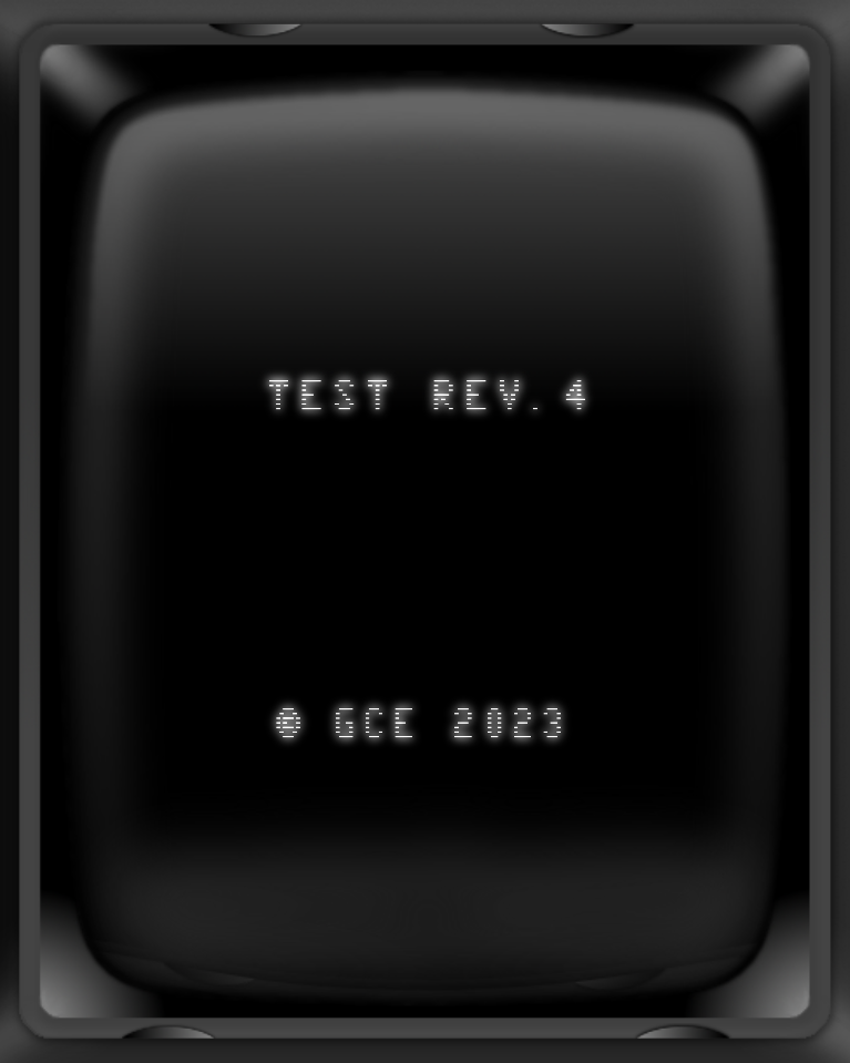
- Digital Archeology - An investigation of the Test
Rev.4 cartridge
- For reasons I won't go into here I
was inspecting the code of the Test Rev. 4
cartridge and somehow ended up with a complete
disassembly and analysis of the code. Here is a
summary of some interesting, yet
probably utterly useless findings...
An
analysis of the Test Rev.4 cartridge
- The code structure shows an interesting
design, using a major jump table and indirect jumps
to the test procedures (function pointers). Looks
like it was built to be easily extended with
additional tests.
- The cartridge code contains copies and slight
modifications of quite a lot of the vectrex BIOS
routines. Some few of those copies are dead
code and not used by the cartridge, but the vast
majority of the copies is actively used instead of
the actual BIOS ROM functions, especially lots of
drawing routines. Of the true BIOS ROM functions,
only DC_to_C8(), Print_Str_hwyx(), Do_Sound(),
Intensity_a(), Recalibrate() and Sound_Byte() are
used.
- The most interesting of the modified versions
of the BIOS routines are the local
Wait_Recal() and Moveto_d() version. The Moveto_d()
version does not contain all those extra delays
which can be found in the BIOS code.
- Some guess work: Most likely the cartridge
code started with just some few tests and versions
of the early BIOS routines, while the BIOS itself
was still being developed. Then later on more tests
were added. It might also be possible that the early
versions of the test cartridge ran on consoles
without a BIOS ROM chip.
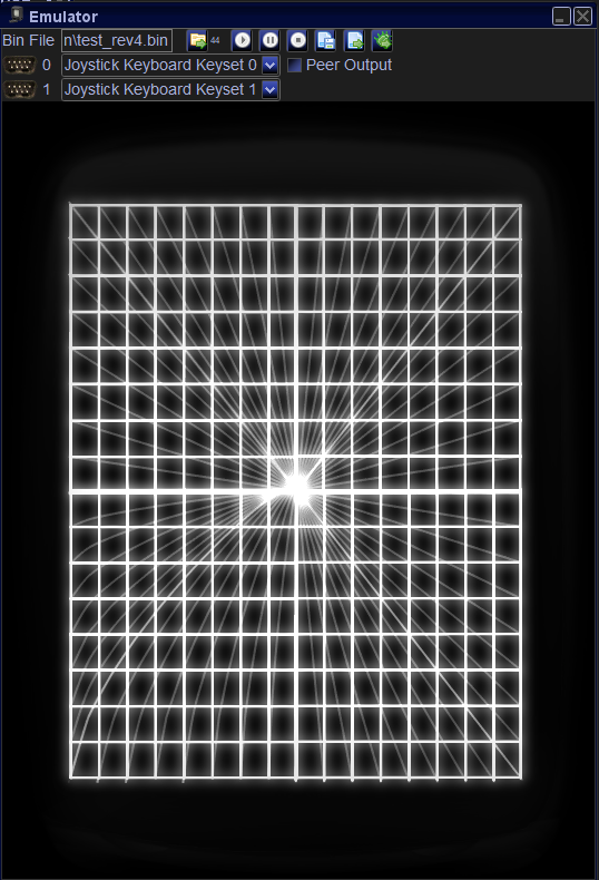
- The initial grid test draws a large 16x16
square grid in a rather inefficient way, with lots
of Moveto() and Reset0Ref() calls, and with complete
lines unnecessarily drawn as repeating segments. I
guess that this is done deliberately, so that on the
screen one gets a good impression of how accurately
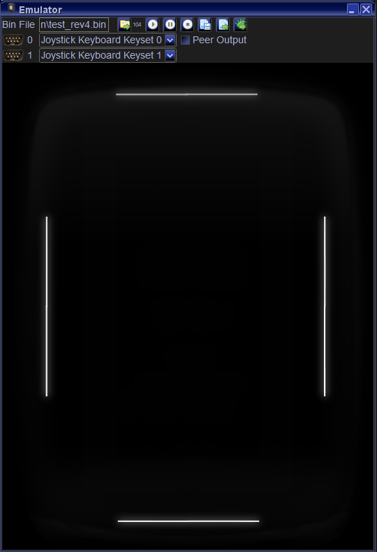
the beam is being positioned. The additional four
outer boundary lines of the grid test are placed at
Y-distances -77 and + 77 from the center, and at
X-distances -64 and +64 from the center. This
translates to a Y : X aspect ratio of 155 : 129 (you
have to figure in the center point, so you get
2*77+1 : 2*64 + 1), which is about 1.2015503. I
think the aim of the designers / programmers was
probably to get as closely as possible to 1.2, which
would correspond to a desired ratio of 6 : 5. Below
are separate pictures of the aspect ratio boundary
lines, and of the square grid, the latter also
showing all the "invisible" moves (thanks Vide!).
- The deflection protect test draws a
hypercube of increasing size with scales from 0 to
255, while using only a Wait() and not a
Recalibrate(). On a real console, this causes the
cubes of the smaller scales from 0 to some threshold
value (maybe ~0xb0==176, at least it seems so on my
consoles, I have not yet tried to determine the
precise value) not to be shown on the CRT. The Wait()
routine essentially keeps ZERO active all the time
while waiting for the timer. If this happens, the
effective brightness of the electron beam on the CRT
is immediately dimmed. If ZERO is active for 20/50
seconds, then the hardware deflection protection
mechanism kicks in disables the screen display. Note
that page
21
of
the Vectrex Service Manual describes the
appearance of this test sligthly different than it is
described on page
8
of
the Vectrex Trouble Shooting Guide.
- You can find further
investigations regarding the deflection protection
mechanism in a related and detailed
analysis of the Wait_Recal() BIOS routine.
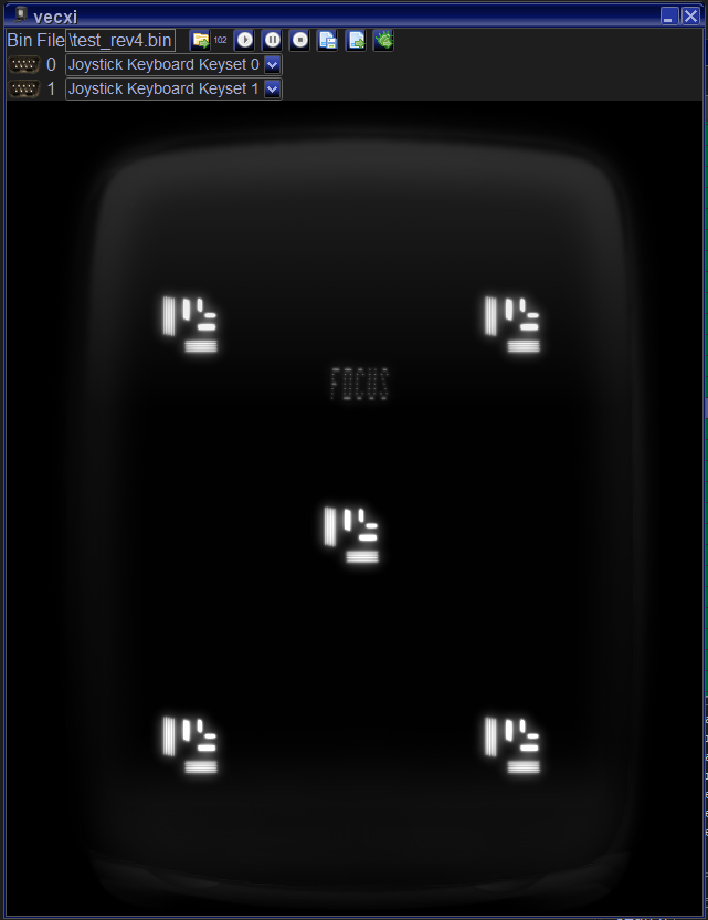
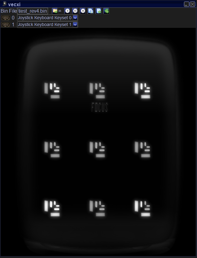
- In the code section of the focus test, there
is data for a total of 9 focus items to be displayed.
However, only the first 5 are used. Likely because the
flicker is already bad with 5. Displaying all 9 items
results in an even more terrible framerate. Here are
pictures of the original 5-items and the hidden
9-items version:
- The checksum is computed for the RUM
code and for the Mine Storm code (complete area
from 0xe000 to 0xffff). I have only access to BIOS
images with checksums 0xb767, 0x7931 and 0x7adb.
The latter two BIOS versions come with the same
Mine Storm version, which is different from the
Mine Storm version of the first BIOS. All three
RUM versions are different (for a deeper analysis
see here).
- The distortion 1 test, for whatever
reason, draws imperfect triangles with start point
and end point not perfectly matching, according to
the vector data. The resulting yx offsets (in
vector coordinates) are (-1,-8) for the left
pointing triangles, (-1,+7) for the right pointing
triangles, (-8,0) for the downwards pointing
triangles, and (-1,0) for the upwards pointing
triangles. If you look closely, these
imperfections can be seen on the real console. Why
did the programmers choose such data? And why with
different imperfections for each type of triangle?
- The distortion 2 test draws 16
rectangles of yx vector size (254, 240), using
scale factors 65 to 125 in steps of 4. This
results in a pattern of the so-called mystery gaps
(for an explanation see here)
of sizes 3,0,4,1,5,2,6,3,0,4,1,5,2,6,3,0 which can
clearly be seen on the screen.
- Most of the test procedures do exceed the 50Hz
framerate barrier, which, on a 220Hz power
grid, leads to some terrible shaking of the
vectors. Here are some more detailed cycle counts:
Test
|
Cycle Count
|
GRID
|
42000
|
ADJUST DAC OFFSET
|
n.a.
(6618)
|
INTEGRATOR OFFSET
|
26612
|
FORMING CHECKSUM
|
<51935
|
DEFLECTION
PROTECT
|
<6860
|
SOUND CHANNELS
|
<7415
|
INTENSITY
|
39113
|
FOCUS
|
42975
|
DISTORTION 1
|
31490
(30378)
|
DISTORTION 2
|
31229
(28871) |
KEYS + JOYSTICKS
|
35153
|
- If there is interest, I will create a modified
version
of the cartridge with most of the tests
running within 50Hz, which can quite easily be
achieved by simply shortening or removing the text
messages of the tests. Except for indicating which
test is currently being run, those are not
important to the actual test procedure. Also, I
will add separate checksum tests for the RUM and
for Mine Storm.
- Some additional new tests, which could also be
added: drift indicator test, showing how
much drift you have on your console, and a DAC
inaccuracy test, showing how prone your DAC
is to the abs(DAC(x)) != abs(DAC(-x)) phenomenon
(monotony errors, see here).
Author
Latest
modification
on
09/14/2024, 15:22
- Section about the
initial grid test added
- Cycles counts
table completed
|